|
Modifications to the Hornby tender chassis |
|
|
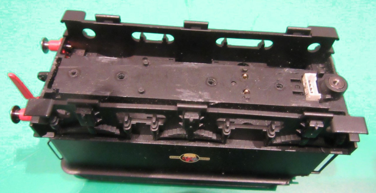
Remove the four screws which hold the plastic tender keeper plate on the bottom of the tender chassis.
This keeper plate will then lift out from the rear and the wheels will be free to be removed. Keep the screws to retain the new etched chassis.
On the main plastic chassis part are six pairs of lugs where the original axles are seated. These need to be removed completely and this is easily done with either a scalpel or a piecing saw. |
 |
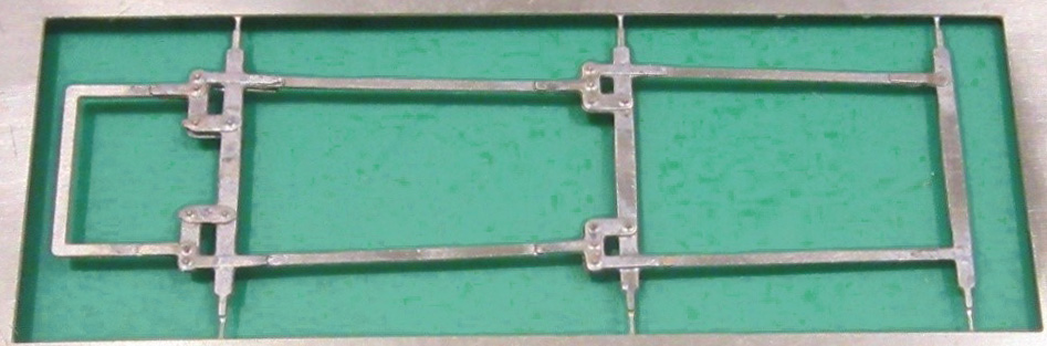
| Main tender chassis etch | |
|
Locate the main chassis etch [T1].
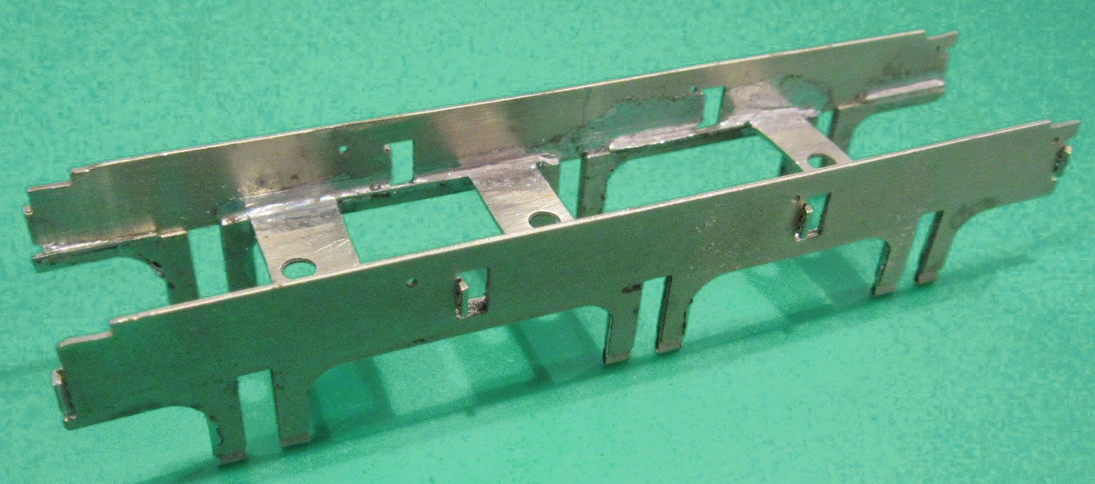
Bend the etch so that the sides fold back on each other, the half-etched line at the bottom of the horn-guides must be on the outside of this bend. Then fold the sides so that the central cross members are at 90 degrees as shown in the photograph.
Solder the side frames together and strengthen the folds between the side members and the cross members. Gently file the sides of the horn-guides to remove the cusp on the etch so that a 2mm axle can run smoothly in the guide.
Bend the supports for the spring wire out by 90 degrees. |
 |
|
Locate the bearing etches [T2]. There are eight of these so there are two spares available. These bearings need to be folded over and soldered. The half-etched side must be on the inside of the bend and the middle of the bend must be at the middle point of the half-etched section. This allows the top of the bearing to be formed of a half-etched loop through which the spring wire can pass. Ensure that the two holes in the bearing line up.
Open the axle hole out to 2mm using a reamer or 2mm drill bit. |
 |
|
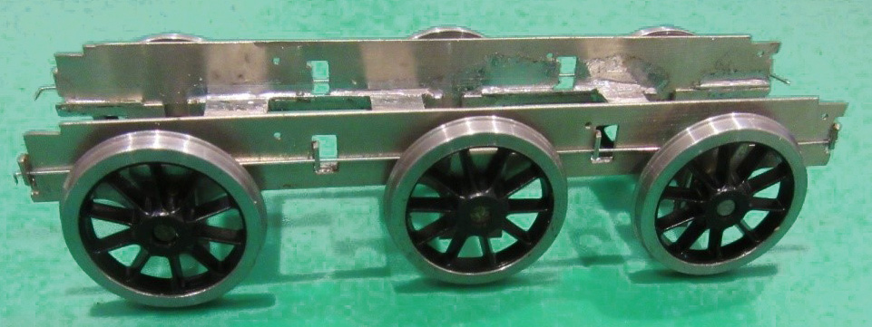
Fit the wheels through the bearings, setting the back-to-back.
Thread the spring wire through the supports on the chassis and through the bearing.
There are two options for the holes in the support brackets.
Use the one nearest the track level, the higher one might be
useful if you are fitting a particularly heavy loudspeaker in the
tender. |
 |
|
Locate the tender brake components [T3] - these fold in exactly the same way as the locomotive brakes. Once again there are a couple of spares on the etch.
Feed a 25mm length of 0.8mm wire through the brake hanger holes in the tender chassis.
The brake hangers need to be spaced off the sides of the tender frames by 2.5mm for P4 or 2mm for EM and this best done by inserting some short lengths of 1.5mm brass tube over the wire.
Cut the tube to length by marking 2 or 2.5mm and then rolling with a heavy Stanley knife until it cuts.
|
 |
|
Locate the tender brake pull rod etch [T4].
The half-etch detail parts need to be soldered on either side and it is much easier to complete this while the etch is still on the fret.
Tin the parts first,
then attach the detail parts. |

|
|
Once the brake pull rods are complete, remove from the fret and slightly round the corners of the ends of the tie rods so that the ends will fit into the holes in the bottom of the brake hangers.
As with the locomotive springs, fitting with temporary pieces of wire insulation will help this process.
Fit the rods into the brake hangers and solder the ends at the top and bottom of the brake hanger.
Remove the central section of the 0.8mm wire between the frames. This will allow the brake assembly to spring off the chassis to allow the wheels to be removed. |
 |
| Tender pick-ups | |
|
Pick-ups can be arranged to spring on the rear of the wheels, and with care the original Hornby pick-ups can be re-used.
A length of copper clad paxolin (sleeper strip or similar) can be glued to the outside of the chassis to solder the pick-up wires to.
While this can be done on both sides it is only strictly necessary one side if you don't object to the chassis etch being live to one rail.
In this case solder the pickup wires on this side to the outside of the chassis
This should not be an issue as the chassis is insulated by the plastic of the Hornby body. |
 |
|
The pick-ups can be made to feed the original sprung studs on the tender body either by using a sprung piece of metal or by soldering directly to the studs.
A short length of phosphor-bronze strip is ideal for this, it can be bent into a rectangular shape with half of the top of the rectangle missing and soldered to paxolin strip or the frames as appropriate.
The photograph shows how this fits. |
 |
 |
|